


Next: Echelle Simulator for IRCS
Up: IRCS ECHELLE SPECTROGRAPH
Previous: IRCS Overview
Most echelle spectrographs operate near the blaze angle ( groove angle) of the echelle grating, near-Littrow or Quasi-Littrow Configuration, to maximize diffraction efficiency and minimize anamorphic magnification.
The incident angle
groove angle) of the echelle grating, near-Littrow or Quasi-Littrow Configuration, to maximize diffraction efficiency and minimize anamorphic magnification.
The incident angle  should be greater than the diffraction angle
  to avoid efficiency loss due to the groove shadowing effect (Schroeder & Hilliard, 1980; Schroeder, 1987).
The IRCS echelle operates around 63 5 with
 8
8 to allow sufficient separation between the incident and diffracted beams in a reasonable distance while keeping the configuration as close as possible to the Littrow condition.
The operating angle of the cross-disperser is about 31 with the incident angle of 24 at the blaze wavelength. These angles were determined somewhat arbitrarily considering the mechanical arrangement of optical elements (Warren, 1996).
to allow sufficient separation between the incident and diffracted beams in a reasonable distance while keeping the configuration as close as possible to the Littrow condition.
The operating angle of the cross-disperser is about 31 with the incident angle of 24 at the blaze wavelength. These angles were determined somewhat arbitrarily considering the mechanical arrangement of optical elements (Warren, 1996).
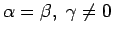
Figure 21 shows the variation of the blaze peak efficiency with the deviant angle from the Littrow configuration for the two gratings of IRCS.
The diffraction efficiency at the blaze peak decreases with
 (see § 2.6), getting steeper as the blaze angle of the grating increases.
The cross-disperser shows about 90 % of efficiency and the echelle shows about 75% of efficiency at the nominal setting.
(see § 2.6), getting steeper as the blaze angle of the grating increases.
The cross-disperser shows about 90 % of efficiency and the echelle shows about 75% of efficiency at the nominal setting.
Although the ``off-plane'' mount (
 ) maximizes the blaze peak efficiency because
  is nearly independent of the peak efficiency (see. §2.6), the IRCS echelle is used ``in-plane'' mount (
 0) because of the following merits:
- In-plane mount makes the distribution of intensity more uniform across the entire wavelength range in each order spectrum due to the flatter blaze function. Such uniformity is important to minimize problems caused by the large contrast of spectral lines over a wide wavelength range. For example, such uniformity requires only small dynamic range of the detector for flat fielding.
It makes comparatively uniform signal-to-noise ratio over the observed wavelength range.
- In-plane mount can avoid complication caused by the variable tilt of spectral lines which occur when
 0. Such tilts make data reduction process complicated.
Figure 21:
Variation of the blaze efficiency with the difference between the incident and blaze angles,
 , or the deviant angle from the Littrow Configuration.
The solid line is for the echelle grating (
, or the deviant angle from the Littrow Configuration.
The solid line is for the echelle grating (
 635) and the dashed line is for the cross-disperser grating (
8016) of IRCS.
The dotted and dashed-dotted lines indicate the initial reference angle between the incident and blaze angles for the echelle grating, 4, and for the cross-disperser, 15984, respectively.
635) and the dashed line is for the cross-disperser grating (
8016) of IRCS.
The dotted and dashed-dotted lines indicate the initial reference angle between the incident and blaze angles for the echelle grating, 4, and for the cross-disperser, 15984, respectively.
![\begin{figure}
\lq
\begin{center}
\includegraphics[width=6in]{BF_Peak_Eff.eps}
\end{center}
\end{figure}](Timg212.png) |
Tae-Soo Pyo
2003-05-29
![\begin{figure}
\lq
\begin{center}
\includegraphics[width=6in]{BF_Peak_Eff.eps}
\end{center}
\end{figure}](img212.png)