Next: Width and length of
Up: Shape of a Slit
Previous: Shape of a Slit
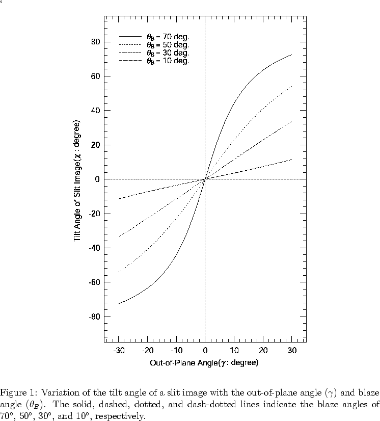
When a straight slit is located parallel to the ruling of a grating, an incident light ray passing through the slit toward the center of the grating has a finite out-of-plane angle ( ) defined by the distance between the position of the ray on the slit and the center.
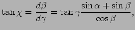
Due to the finite out-of-plane angle, the monochromatic slit image becomes tilted and curved (Figure 5). The tilt angle on the image is given as follows (Schroeder, 1987).
) defined by the distance between the position of the ray on the slit and the center.
Due to the finite out-of-plane angle, the monochromatic slit image becomes tilted and curved (Figure 5). The tilt angle on the image is given as follows (Schroeder, 1987).
 |
(15) |
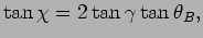
For the Littrow configuration (
 ),
),
 |
(16) |
at the blaze wavelength. Figure 6 shows that the tilt of a slit image is sensitive to the out-of-plane angle when the blaze angle of the grating is large.
Assuming that is small and integrating Eq. 15, we obtain
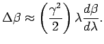 |
(17) |
The slit image thus has a parabolic shape (Schroeder, 1987; Meaburn et al., 1984).
For a short slit, the slit image can be approximated by a tilted straight line.
Figure 7 shows the variation of the tilt angle with the diffraction angle for an R2.0 echelle grating.
It shows that the tilt angle becomes steeper with the diffraction angle when  increases.
The tilted slit images complicate the reduction of a spectrum.
It can be corrected by rotating the entrance slit by the angle  .
In this case, however, the spectral resolution is reduced because the entrance slit width along the direction of echelle dispersion increases by
.
In this case, however, the spectral resolution is reduced because the entrance slit width along the direction of echelle dispersion increases by
 .
In order not to reduce the spectral resolution, it is necessary to narrow the slit width by a factor of
.
In order not to reduce the spectral resolution, it is necessary to narrow the slit width by a factor of  .
This in turn reduces the flux by and consequently the resolution-slit width product, i.e., the throughput, decreases by a factor of (Schroeder & Hilliard, 1980).
.
This in turn reduces the flux by and consequently the resolution-slit width product, i.e., the throughput, decreases by a factor of (Schroeder & Hilliard, 1980).
Figure 5:
Tilt and curvature of a slit image.
![\begin{figure}
\lq
\begin{center}
\includegraphics[width=6in]{Slit_curvature.eps}
\end{center}
\end{figure}](Timg104.png) |
Figure 7:
Variation of the tilt angle of slit images with diffraction angle for an R2.0 (blaze angle  63
63 5) echelle grating.
The solid, long-dashed, short-dashed, and dotted lines indicate the out-of-plane angle of 00, 10, 25, and 50, respectively
5) echelle grating.
The solid, long-dashed, short-dashed, and dotted lines indicate the out-of-plane angle of 00, 10, 25, and 50, respectively
![\begin{figure}
\lq
\begin{center}
\includegraphics[width=4in]{tilt_beta.eps}
\end{center}
\end{figure}](Timg106.png) |
Tae-Soo Pyo
2003-05-29
![\begin{figure}
\lq
\begin{center}
\includegraphics[width=4in]{tilt_beta.eps}
\end{center}
\end{figure}](img106.png)
![\begin{figure}
\lq
\begin{center}
\includegraphics[width=6in]{Slit_curvature.eps}
\end{center}
\end{figure}](img104.png)