


Next: ECHELLE SPECTROGRAPH BASICS
Up: IRCS_reduction_html
Previous: List of Tables
MERITS OF CROSS-DISPERSED
ECHELLE SPECTROGRAPHS
A useful figure of merit for a grating spectrograph is its throughput, which is the spectral resolving power multiplied by its entrance slit width (Vogt, 1987).
It is given by
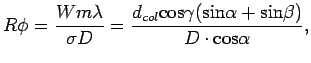 |
(1) |
where  is the resolving power,
  is the entrance slit width projected on the sky (radian),
  is the projected length of the collimated beam on the grating,
  is the wavelength of order number
  ,
,  is the groove spacing of the grating,
  is the diameter of the telescope primary,
  is the collimated beam diameter,
  and
and  are the angles of incidence and diffraction, respectively, and
  is the out-of-plane angle (Figure 1 and 2).
For the Littrow case (
is the out-of-plane angle (Figure 1 and 2).
For the Littrow case (
 )
)
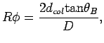 |
(2) |
where  is the blaze angle of the grating.
In order to achieve a larger throughput, a larger beam size and blaze angle are required.
The beam size becomes the largest when the focal ratio of the collimator equals the effective focal ratio of the telescope, i.e.,
 .
.
An echelle grating has a large blaze angle and has high throughput compared to the other conventional diffraction gratings of the same size.
Moreover, it is possible to utilize two-dimensional detector array space more efficiently by using a cross-disperser for order separation.
The cross-disperser disperses the spectrum into the direction perpendicular to the echelle dispersion, allowing us to cover wide spectral ranges with a single exposure.
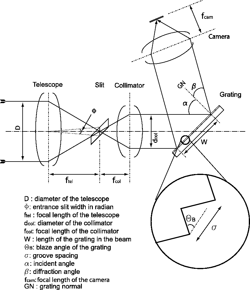
Figure 1:
Schematic drawing of a slit spectrograph with a reflection grating.
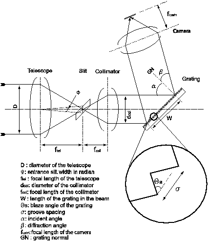 |
Figure 2:
Schematic showing angles of incident angle , diffraction angle , and out-of-plane angle .
![\begin{figure}
\lq
\begin{center}
\includegraphics[width=6in]{Echelle_conf.eps}
\end{center}
\end{figure}](Timg40.png) |
Tae-Soo Pyo
2003-05-29
![\begin{figure}
\lq
\begin{center}
\includegraphics[width=6in]{Echelle_conf.eps}
\end{center}
\end{figure}](img40.png)